Bedside CPAP Layout: Table Space and Hose Routing
Compare bedside surfaces for a CPAP device and map the hose and access route, while checking the exact device instructions and individual needs.
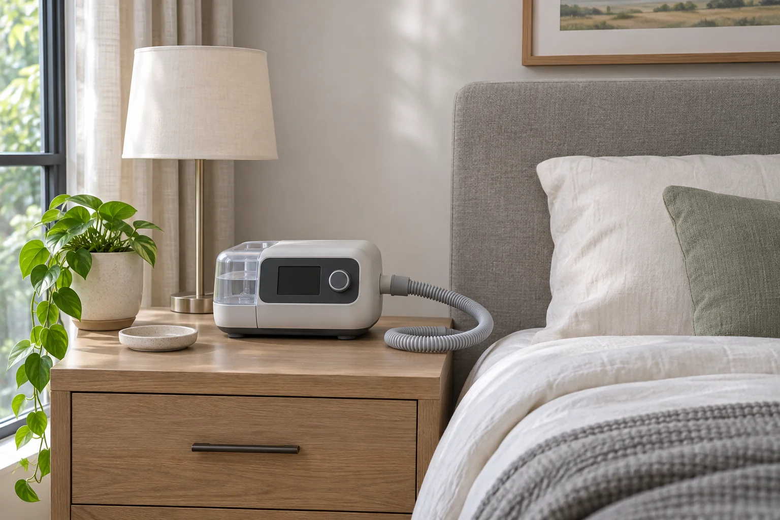
Bedside device footprint on two surfaces
A places a 220 × 180 mm footprint 60 mm from both reference edges on a 450 × 350 mm surface. B uses the same placement on 300 × 240 mm, with 20 mm right and zero front clearance. Verify the real equipment instructions separately.
Two bedside tables can look equally suitable in a furniture listing. One leaves room to reach along the front and the other keeps more of the floor open beside the bed. The more useful question for a household arranging a CPAP device is which requirements change when the whole bedside area is put back together. Begin by identifying the existing equipment, its instructions and the way the person enters and leaves the bed. Compare the tables after those facts are visible.
Treat this as a furniture and access drawing. Take measurements with the user's agreement, according to the equipment instructions, without disturbing treatment. An unconnected outline can stand in for the machine or hose when comparing positions. Questions about hose configuration, equipment changes, operation or therapy belong with the manufacturer, equipment provider or care team as appropriate. The page offers no medical assessment of a proposed layout.
Put the requirements in order before looking at finishes
First, make a place for the specified equipment. Translate the actual placement and support instructions into conditions that are visible on the furniture drawing. Mark dimensions as outstanding when the instructions or equipment details are unavailable. A table does not become a candidate simply because its photograph shows an open surface.
Next, preserve the user's ordinary movement. Draw how the person approaches the bed, where they stand, and what they need to see or reach. Note whether access for regular care of the equipment uses a different direction. Reserve room for those actions when comparing two footprints.
Then, compare hose and power routes as separate lines. Describe the movement of the user, bed and nearby objects around those lines. Where the instructions do not resolve an issue involving the actual device or hose, request guidance before committing to a furniture location.
Finally, consider the appearance and secondary use of the table. A lamp, drawer, clock or decorative screen should be compared in the same plan as the equipment. Those objects can be moved or selected after the necessary areas are known. A finish choice is easier to change than a piece of furniture with little usable support space.
The order helps when two priorities conflict. A narrower table can preserve a good approach to the bed while making a routine access position unavailable. A broader one can keep equipment and other objects apart while increasing its projection into the aisle. Rather than choosing by nominal size, write down which condition is actually affected and who can determine whether the remaining option is appropriate.
Compare the usable surface, then inspect what the rectangle omits
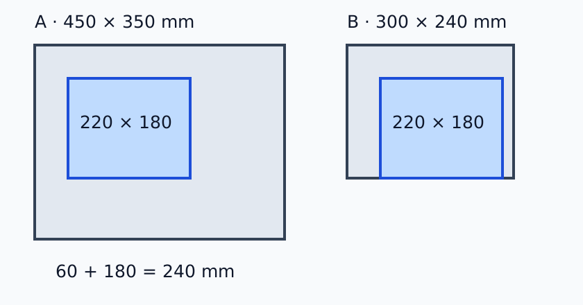
Open the full-size surface comparison
A hypothetical device footprint is 220 × 180 mm, placed 60 mm from the left and rear edges of a usable 450 × 350 mm surface. The right difference is 450 − 60 − 220 = 170 mm, and the front difference is 350 − 60 − 180 = 110 mm. For B, keep the device and offsets but reduce the usable surface to 300 × 240 mm. The right difference becomes 20 mm and the front difference becomes zero. Zero means the simplified footprint touches that edge; it is not a recommended tolerance.
The drawing omits feet, power and hose connectors, ventilation, water chamber, and the motion needed to operate or clean the device. B's arithmetic containment does not demonstrate a stable or approved installation. A larger surface uses more bedside space, which can affect walking and drawer access. Compare the complete actual equipment and any manufacturer-required clearances rather than ordering from the bare case dimensions.
Give the measurement a real reference edge
For the teaching rectangle, left and rear edges serve as references. At home, identify which furniture edges actually bound the surface that can support the equipment as specified. A table advertised as 450 mm wide may have a raised border, an opening around the back or tapered corners. A shelf inset into its frame may have a smaller usable area than the projecting feet or overhanging top visible in a plan. Measure the surface itself at the proposed position. Separately mark any part of the furniture, including the base, that protrudes into the user's route.
Draw the rear edge and find its actual relationship to adjacent furniture or the wall. The back of the table may not sit against a flat uninterrupted surface. Skirting, a bedside panel or a wall outlet can move the table forward or make part of the top unusable for the assumed orientation. Do not infer that an offset in the diagram will equal a distance from an actual wall. When you compare two tables, apply the same reference convention and record any fixed projections that move it.
The device footprint should have an equally clear definition. Inventory the dimensions that can be taken from the exact manufacturer's information or measured under the permitted conditions: overall outline, contact points, connector projection and any described clear zones. Those are different layers of the drawing. If a casing does not touch the surface everywhere below it, the required support still comes from the manufacturer's directions. Check the furniture information too: its condition, support arrangement and permitted use. A rectangle on paper cannot determine how a surface behaves under equipment.
Work through A and B without silently moving the device
The useful controlled comparison leaves a 220 × 180 mm outline and the left and rear offsets of 60 mm unchanged. Tightening the table first from 450 to 300 mm in width takes 150 mm out of the right-side gap; the original 170 becomes 20 mm. Changing usable depth from 350 to 240 mm takes 110 mm out of the front gap, reducing it to zero. Front and right reflect distinct axes. If the reduced front gap is the reason a proposal needs review, a wider but equally shallow table doesn't by itself change the arithmetic at the front.
It can be tempting to shift B's device outline backward on the drawing until the front gap turns positive. A changed offset is legitimate as its own teaching comparison. In the actual room it also changes the rear edge relationship, the location of the power and hose connections and possibly an instruction-defined separation. Write the proposed move as a separate configuration. Leave any missing clearance requirement unresolved until the exact model and orientation are known, rather than balancing numbers against an imagined requirement.
If dimensions are quoted to a furniture supplier, say where each was taken. “Usable top measured inside the raised lip” and “full footprint of the table with the legs” are two separate requirements people may need to check. Give the measured equipment outline and the actual means of support only as documented. If a drawer or a door below the top is part of the plan, also send the direction and depth of its opening. A top that contains a rectangle can be deep enough in plan while an open drawer occupies the approach reserved for the user.
Keep the space needed to handle things separate from the resting silhouette
Use one outline for the case sitting on the table and a different mark for the activity that has to happen beside it. For example, a household may need occasional access to a part identified in the equipment instructions. The furniture question is whether that part can be reached and whether there is an appropriate surface nearby to receive what must be set down. Follow the manufacturer's sequence rather than improvising an operation for the purposes of the test. You can represent the action on the drawing or with an empty outline. If the action is unclear, ask the equipment provider what spatial conditions are needed.
On a bedside table with a back panel, the daily operation may occur from the front but the accessible space for a connector may be to the side. Check which side has an approaching hand, where the user needs to stand, and whether a bed frame or a wall lies next to it. This is not a reason to move the connector or choose a different hose. The drawing shows which surfaces and directions the selected furniture gives access to. Any actual equipment handling still follows the instructions for the device and supplied parts.
Clear zones are best labeled by source. Manufacturer instructions might address specific openings, orientation or installation conditions. The user's preferences or accessibility needs might identify an approach space, an item they want nearby or a direction from which labels should be visible. The furniture documentation might describe a suitable load-bearing surface or assembly requirement. Where the sources do not answer a question, retain that question explicitly. For a household arranging an existing device, identifying the missing authority is often more useful than adding a guessed margin around the entire rectangle.
Draw a side view where two levels collide
A table and bedside object can be separated in plan yet interact at another height. A projecting bed frame might prevent the table base reaching the planned line. A hanging portion of bedding can come closer to the equipment surface than the frame does. A wall feature may occupy the height of the top rather than the legs. For the space being considered, draw one side section with the finished floor as the common datum. Add the lowest and highest physical parts that affect the table's placement. If the room includes a window ledge, cabinet next to the bed or furniture handles, check their projections in the same section.
Mark which dimensions describe the proposed furniture and which ones describe the fixed room. The assumed top on a sketch does not show its legs or any lower braces. A smaller top with splayed legs might occupy more of the floor than a larger one with a contained base. A shelf fitted between pieces of furniture could appear to save floor area while leaving no approach to one side of the equipment. Compare both the resting footprint and any approach space on the same wall section without interpreting the result as evidence about device operation.
If the user wants lighting or a clock near the same spot, include its position at the height where it would actually be used. A wall item can be off the tabletop and still reduce the space for a hand or the view of the controls. Show the furniture alternatives with only compatible arrangements under consideration. A vendor drawing can establish dimensions, but the actual user can point out the angle from which they approach the table. Where the comparison needs an equipment requirement, ask for that requirement before concluding that a different furniture height will work.
Follow the hose and the person's movement
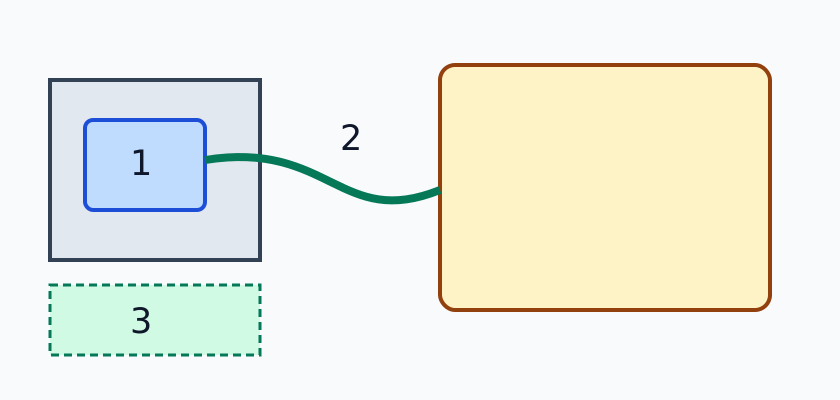
Open the full-size route sketch
Number 1 is the device, 2 is an illustrative hose route and 3 is a separate access zone for controls or routine care. The curve is not a recommended hose route or a prediction of slack. Check it against the person's ordinary turning, getting out of bed and reaching for controls, without pulling a connected hose or changing therapy. The table, bedding, hose and power supply must follow the specific product's instructions.
Draw the room before drawing the hose
Put the bed frame, edge of the mattress, bedside furniture, nearby doorway and usual walking side on the plan. If one part of the bed extends beyond another, show that projection at the level where it matters. A mattress edge tells you where a person approaches the bed; a projecting frame or drawer pull may be what they meet on the way. Add the position of any object regularly moved in that part of the room, such as bedding or a chair. Ask the user before including personal equipment or movement details in a plan shared beyond the household.
Show two situations that are relevant to normal furniture use. A closed bedside drawer with bedding arranged is a useful starting picture. An open drawer or hanging bedding creates a second geometry. For an adjustable bed or movable furniture, use only the ordinary positions and motion understood by the user and indicated by the equipment or furniture instructions. You can compare the furniture dimensions with the actual working device left untouched, and use a separate outline or loose line elsewhere on the plan to explain where a route might need resolution.
Keep the person's path separate from lines on the floor that represent stored items. A lightly colored line on a drawing can be mistaken for something that can be stepped over. In the room, the proposed path for the person should remain available as required by their situation. Ask the user what tends to move near the bed and whether any familiar path gets narrower when the table is moved sideways. Record any concern requiring the provider or care team rather than deciding a clearance from a generic example.
Describe route concerns by what crosses them
The curve in the figure illustrates what a reader can follow with a finger, not an instruction to choose a route, tension, clearance or attachment method. Place the intended device position on the diagram and, using guidance for the exact equipment, draw the proposed vicinity of its hose route. Ask which other routine movements would pass there. A table drawer can move into that area from the side. Bed linen can hang into it from above. A person approaching the bed may stand between the furniture and the mattress. A sketch of a curve on a table cannot specify how the actual hose should be routed around any of those states.
Write a separate label for the point where the visual route approaches another surface. “Drawer front and projected hose area overlap when the drawer is open” is useful for reviewing the table arrangement. “Fix the hose to the drawer side” would be an equipment decision beyond the spatial evidence. If the provider gives approved routing, support or positioning options, capture the exact instructions and reconsider the furniture around them. Unresolved points should remain questions rather than being worked around with a makeshift accessory.
The power route has its own references and conditions. Identify the room outlet and the place the device instructions require for its connection. Note what furniture could cover the outlet or make it physically difficult to reach. Check the area where the line would share space with walking, a drawer or an adjustable bed element, without proposing unverified alterations or connections. If the available outlet and equipment directions cannot be reconciled with the candidate table, that is a reason to pause the layout comparison and obtain appropriate advice.
Look at bedside access in ordinary room conditions
Access at night starts with familiar room geometry. Ask the user whether the bedside area is approached from the doorway, a nearby chair or another side of the bed. Note the orientation from which the person needs to recognize the relevant part of the device or find the room's usual controls. Test visibility of the furniture and the unconnected mock-up under ordinary lighting only when the user agrees and can take part comfortably. You do not need to ask them to simulate sleep, change their device use or participate in a move that affects treatment.
The space at the bedside also has work during the day: linens are changed, the floor is cleaned, an outlet may need to be inspected and the bedside surface has to be reached. List which items are expected to stay where they are during those tasks. If the current table is frequently pulled out, consider how choosing a new table would change the room's use and confirm any equipment questions with the provider. A narrower table that can remain stationary under the instructions may be more useful than one that is repeatedly moved to open a drawer. That decision still depends on finding a compliant, accessible location for the actual equipment.
Check a shared room from both directions
In a bedroom shared by two people, a second approach can use the same passage at a different time. Ask each person to point out their normal doorway and belongings without treating either person's routine as a measurement of the other's. If a chair or basket is usually moved to let one person pass, show its intended resting place too. A layout which depends on a removable object being left outside the room should be compared with ordinary days when it is used. Keep the proposed equipment and its specified position out of any rearrangement made merely for the sketch.
Changing sheets can require access at a corner that looks empty in a furnished photograph. Mark that action separately from the user's getting-up path, and see whether it would demand a change near the planned device. If an object will need to move near the equipment, identify the issue for the equipment provider or appropriate instructions rather than practicing the change with the device in use. This kind of room planning can reveal whether a piece of everyday furniture could remain fixed in a different position and leave two routes available.
If a second person helps organize or clean the room, hand them a copy of the drawing with just the details they need. A helper can identify the furniture parts, surface and space that should stay clear without receiving personal treatment details. Keep sensitive information for the appropriate parties. Use a note such as “check this edge before opening the drawer” only for a furniture observation, and refer questions about the equipment itself to its documentation and the appropriate people.
When a stretch of floor serves as the room's only approach, draw it continuously from the doorway to the bed. A bench or basket outside the immediate bedside corner may consume the same space the narrow table would save. Show where that ordinary furniture could actually go before awarding its empty patch of floor to another use. Document which positions were compared with the usual belongings in the room. This makes the narrower table, the larger table and moving a separate piece of furniture comparable without making guesses about changes to the equipment.
Make a two-layer comparison instead of awarding points
| Room question | Evidence in A or B | Who can settle an unresolved item |
|---|---|---|
| Is the usable surface clear of the footprint at the recorded offsets? | Measured top, device outline and reference edges | The household can measure; equipment instructions determine required support and conditions |
| Can ordinary standing or circulation take place by the bed? | Outline of the bed, furniture base, moving drawer and positions the user identifies | The user and, if needed, appropriate accessibility support |
| Does a routine activity pass near the proposed hose area? | Overlay of the activity and the proposed vicinity from the actual layout | Equipment provider or care team for the equipment implications |
| Can the indicated parts be reached for operation or care? | A separate activity outline plus the manufacturer's item or direction | Device directions or provider |
| Does the outlet location conflict with the furniture? | Outlet, reachable area and furniture projections | Equipment directions and qualified electrical help when required |
These questions do not combine into a numerical rating. An attractive table can satisfy four geometry checks and still leave the appropriate arrangement unresolved because the necessary clearance at a specific opening is unknown. Mark that condition waiting instead of assuming another positive item compensates. This is especially important when people compare a table on a shopping page and can't see its rear construction or support details.
Prioritize requirements before appearance
- With the equipment safely disconnected as instructed, inventory the actual device, feet, attached connectors, hose and any accessories. Record the usable support surface, not the nominal outer table size; leave unknowns blank.
- Compare the manufacturer's placement, ventilation, water handling and cleaning instructions for the exact model with each candidate position. Do not block openings or improvise electrical arrangements; seek qualified help when needed.
- Using an unconnected mock-up, trace the route around the bed and check how the user can reach the controls and get up. Ask the user and care team about issues involving the equipment or therapy; stop if the proposed position introduces a snag or uncomfortable action.
- Use the surface comparison to change the surface, footprint and offsets. Negative numbers show that the rectangle extends outside the selected surface; positive numbers do not establish support, ventilation, hose safety or medical suitability.
- Check the furniture and its unconnected outline under the room's ordinary conditions, with the user's consent. Document unresolved questions and follow the exact device instructions before making any change involving the equipment.
Work through common furniture trade-offs
The larger top narrows the walking side
A larger top can leave more space at the front of the outline; the geometry of A illustrates that. Check whether the whole table advances toward the walking side, or whether the wide portion is actually at the level of the top while the base has a different footprint. Trace the narrow place with the furniture in position and the adjacent door used as intended. An open bedside drawer may be the controlling feature at one time and the cabinet side may matter at another. Record both rather than replacing the walking path with a minimum number from an unrelated house plan.
For example, suppose B fits along the wall and leaves a more open approach to the bed, while its front gap reads zero in the section. The arithmetic tells you to investigate the relationship at the front. It doesn't prove B should be used or that A isn't feasible. Consider another depth or a different furniture arrangement without proposing adjustments to the machine. If nearby removable furnishings are the main obstruction, drawing their alternatives can preserve the user's approach while letting the equipment conditions determine the table.
Open shelf, drawer or second surface
If considering an open shelf instead of a table top, compare its truly usable width, clear opening, supporting details and access to the exact device. A photograph may show three open sides while the shelf actually has a rear cross brace or a top above it. Consult the device's placement and ventilation instructions before treating that as a candidate. A drawer is useful for ordinary household storage, but show how its movement and contents overlap the approach. Do not treat an enclosed drawer or cupboard as an equipment location unless the relevant product instructions actually address and permit the arrangement.
Sometimes a second furniture surface lets the bedside table hold fewer household objects. A reading lamp can be separated from the equipment area if the room and its existing infrastructure allow it. A device surface still needs space for the user and the activities associated with it. Draw each item's ordinary place when comparing options. A clock or other item set in the front gap of A could occupy the apparent advantage even though the exterior table size is unchanged. Make sure any alternative tabletop use is stated in the final layout.
Repositioning one piece can move several boundaries
Moving the table closer to the bed can create a wider walking area on its outer side and a narrower gap inside. Account for the bed frame, soft furnishings and the parts of the table at the points that now approach them. A side of the top may be closer to a duvet in ordinary use than when the bed has been completely cleared for drawing. A power outlet may move into or out of the working area as a table changes location. Keep the bed itself in its ordinary position for the comparison unless the user has a separate furniture plan they want to examine.
When weighing a different table height, measure what the user would have to reach and what now intersects the device area. A shorter piece of furniture can be proposed to keep its top below a wall feature, but the allowable place for the actual device comes from its own instructions and the provider. Do not assign a generic table height or a vertical hose relationship from a layout article. Record the top height, the top's position relative to the floor and the approach in the usual room setup, and present that comparison for the appropriate review.
Keep model substitution and clinical decisions outside the furniture drawing
A proposed table can also be affected by a future supplier substitution. If it will be delivered with a revised top, ask for its usable dimensions and actual openings again. A worktop lip not shown in the original image can change the rectangle used in the comparison. When the equipment configuration itself changes for reasons handled by the user's provider, revisit the furniture with the new exact instructions rather than assuming the former footprint and access requirements transfer. Property or furniture changes are within this drawing's scope; recommendations about settings, tubing types, clinical suitability and equipment substitutions remain outside it.
Compare a plausible third furniture arrangement
Consider a strictly illustrative arrangement C with a usable 360 × 300 mm rectangular top, the same 220 × 180 mm outline and the same two 60 mm offsets. The right difference is 80 mm and the front difference is 60 mm. This computation reduces both of A's free differences while avoiding B's front contact in the simplified rectangle. It supplies a three-way furniture comparison without suggesting any required number. In a real room, C still needs suitable support, the manufacturer's conditions and a user approach. Its smaller top does not identify how the furniture base will occupy the aisle.
Now change one feature at a time. If a raised front lip makes 15 mm of depth unusable at the same location, the front difference in C would change from 60 to 45 mm when the rear reference is unchanged. That small detail changes a footprint comparison even though the outer top dimensions can stay identical. Conversely, a table leg moved farther into the room can change the person's path while leaving the model's dimensions untouched. This is how a positive result can coexist with an unsatisfactory furniture arrangement. The arithmetic explains the affected layer; the room survey explains the other one.
You don't need a third model when you have one location that can already be verified. A third is useful when the first two show different unresolved questions. Ask what value genuinely needs to be measured next, such as the rear rail dimension on an open shelf or the radius of a top's corners. If comparing candidates returns only measurements that don't address a documented requirement, pause. The next question may need an answer from the equipment provider before any result is meaningful.
Use a mock-up to settle spatial unknowns
Prepare an outline of the equipment from the documented dimensions. Keep the shape simple enough to move easily, and distinguish the measured outline from the note of where the manufacturer's clear zone begins. Place it on the candidate surface without rearranging the user's real device. If only dimensions of the proposed table are available, reproduce the top's usable boundary and mark the reported height and base projection. Wherever the outline omits a connector or accessory, add a clearly labeled estimate only to illustrate uncertainty or leave it blank. Don't let a generic model be interpreted as an installed configuration.
Ask the person who uses the room to indicate where they would normally walk and stand, without asking them to put on or move equipment for the test. Adjust the mock-up within the limits appropriate for comparing furniture and observe which parts of the room have to move. Mark a separate position in which someone can carry out the spatial part of ordinary cleaning with the unit left as specified. A light sketch near the floor may show a table leg or wall projection that isn't visible from a view of the top.
A retailer or installer should receive dimensions that they can repeat. An illustrative note might read, “The proposed top is 450 × 350 mm measured within the raised border. The outline is 220 × 180 mm at a 60 mm offset from each reference edge, leaving arithmetic differences of 170 mm to the right and 110 mm at the front. The connector envelopes, support conditions, clear zones and access arrangements are separate points under review.” On an actual project, replace every sample dimension with measured or documented information and identify the exact source. Don't ask the supplier to choose an equipment location from the furniture dimensions alone.
When recording an unanswered question, identify the object, location and ordinary action involved. “The open drawer approaches the proposed line beside the left edge of the bed” tells the equipment provider and furniture supplier what each needs to inspect. A blanket statement that the setup needs more room doesn't distinguish changing the drawer swing from changing the proposed device location. If a dimension is uncertain because the table cannot be measured before delivery, identify the product drawing used and the exact point to confirm before installation. If a separate piece of furniture is required for belongings, note where its dimensions will be checked in the same room plan. These notes make the furniture purchase traceable without including any information about the person's diagnosis.
Use the comparison tool to isolate a geometric question. Change only the table depth while keeping the other teaching values constant to see why the front edge closes. Then change the width in a separate comparison to see why the right side still shows 20 mm on B. Two axis values can be subtracted independently even though the room arrangement depends on all the objects at once. The left and rear offsets are reference distances, and zero at the remaining edge marks contact in the simplified rectangle. Keep each result next to the spatial question it can address.
Finish with an evidence list worth handing over
Before anyone orders furniture, mark one status beside each matter: documented by the exact product, measured on the existing furniture, observed with an unconnected mock-up, or awaiting an answer. A clear question might be whether a specific shelf's rear edge overlaps an instruction-defined clearance. A broader question might be whether the only path available at the bedside should be reviewed with an appropriate specialist. Assign the proper source rather than assuming the person supplying the table can settle equipment or access requirements.
Close the comparison by confirming the person's ordinary room use. The furniture drawing should show why one location helps, which movement it preserves and what remains dependent on the provider or manufacturer. Keep the exact model information with observations for the household, and share personal information only with the people who need it and with the user's agreement. The useful handover is a plan where each rectangle, access area and unresolved line has a named purpose. It lets the person arranging the bedroom change furniture choices without presenting that change as a conclusion about therapy.
For the larger room arrangement, see the bedside table layout guide. The comparison resets on reload and does not store personal information.
TRY THE EXAMPLE
Compare a device footprint on the table
Enter the measured usable surface, full relevant footprint and offset from the left and rear edges, in millimetres. This tests a flat rectangle only.
Allowed range: 1–3000 · Step: 1
Allowed range: 1–3000 · Step: 1
Allowed range: 1–1500 · Step: 1
Allowed range: 1–1500 · Step: 1
Allowed range: 0–3000 · Step: 1
Allowed range: 0–3000 · Step: 1
Positive remainder under these assumptions. Check the actual use and product requirements before choosing a layout.
- West remainder
- 60 mm
- East remainder
- 170 mm
- North remainder
- 60 mm
- South remainder
- 110 mm
Reference boundary — Usable surface width: 450 mm × 350 mm
Blue dashed line: comparison boundary. Red dimension: shortage.
450 × 350 mm
Check feet, connections, ventilation, hose path and the exact equipment instructions separately. Do not infer medical suitability from the rectangles.
Teaching assumptions, not a surveyed home or a construction check. Results describe this simplified geometry or budget only. Changes stay on this page and reset on reload.