Laptop Dock Cable Too Short? Trace the Desk Route
Diagnose a taut laptop dock cable by measuring its real route and movement, then compare dock positions without treating spare length as connector safety.
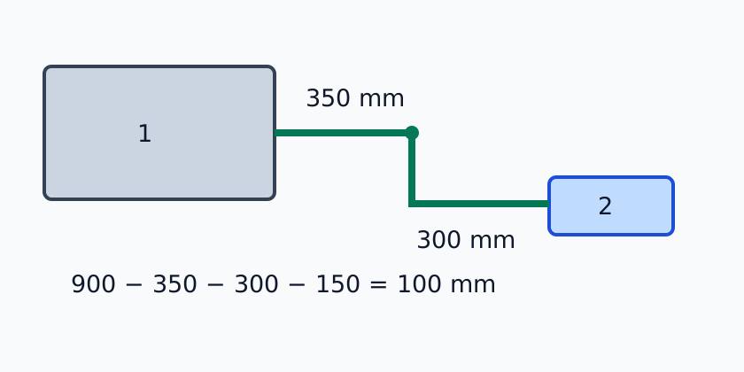
Measured cable segments at two laptop positions
A routes 350 + 300 mm and B routes 500 + 300 mm. Starting from a 900 mm cable and reserving 150 mm separately, the teaching balances are 100 mm and −50 mm.
The laptop moves a little when you push it into its work position. Is the cable actually too short, or did a clip, connector or dock move the point from which the cable can feed? You can diagnose most layout problems by finding the first position that changes the shape of the route. Start with the moment the pull appears. A cable that has no spare length when the laptop is on its stand has a different layout problem from one that is pulled only when the desk rises or the plug is being removed.
Disconnect equipment as directed by the manufacturer before moving it or trying a string trace. As you work through the diagnosis below, keep a note of the first object that moves when it should stay put. Record whether the outer cable straightens, the housing approaches an edge, the dock shifts or another cable attached to the dock becomes taut. You want a cause that can be observed again with a dry layout rehearsal before you order parts or attach a permanent cable tray.
Describe the symptom as an action: “As I lift the laptop onto the riser, the lead straightens between the port and the rear clip.” That is a useful report. “I need a longer cable” is a possible solution that has not yet been tested.
Start with the symptom, then isolate the shortest useful check
| What happens | First place to look | Compare before changing equipment |
|---|---|---|
| The laptop moves when it is placed in its working position | Length from laptop to first fixed guide | The same machine at its working height with the cable path unconstrained |
| The dock shifts when a plug is removed | Grip space at the connector, support below the dock and drag from its other leads | An unplugged rehearsal with the dock supported in an accessible position |
| A plug housing lies against the desk edge | Physical projection at the port and the cable's departure direction | A route that lets the housing and cable leave the port without that contact |
| The cable has spare length on the floor but is taut at the laptop | A clip, tray edge or bundle separating the spare length from the moving segment | Two measurements on either side of the fixed point |
| The problem begins only when the desk changes height | The boundary between the part that rises and the part that stays still | The geometry at the ends and through the range, with equipment disconnected |
Choose the row closest to the symptom and test that part first. More than one can be true. For example, a dock can shift because a cable at its far side has been routed below a shelf, while the laptop cable already has spare length. The clue is the order of movement: if the dock rotates before the laptop moves, include the dock's connections and support in the investigation. If a weekly rearrangement causes the problem, reproduce the changed objects one at a time. Desk accessories and docking equipment often share the same cable space even though they are purchased on different days.
Digital symptoms need their own track. A connection that drops in a particular position might coincide with a visibly stressed route, but a measured surplus cannot diagnose software, port function, equipment compatibility or signal quality. Record any repeatable connection issue separately from a visible contact or taut segment, and follow the equipment manufacturer's troubleshooting instructions for that issue. You can shorten a route or expose a plug for easier handling without drawing an electrical conclusion.
Trace the route the cable actually follows
Open the full-size cable route
In this teaching example, 1 is the laptop and 2 is the dock. The cable's usable length between connector reference points is 900 mm. Its chosen route uses 350 mm to an intermediate point and 300 mm from there to the dock. With a separately chosen 150 mm allowance for movement and bends, the arithmetic balance is 900 − 350 − 300 − 150 = 100 mm. The drawing is schematic: a real cable curves, connector housings have length, and the chosen allowance is not a universal bend-radius specification.
If the laptop is moved so the first route segment grows to 500 mm, while the second segment and allowance stay unchanged, the balance becomes 900 − 500 − 300 − 150 = −50 mm. The proposed allocation exceeds cable length. Moving the dock closer can restore arithmetic length but may consume desk area or make its ports harder to reach. The result does not predict signal quality, mechanical strain or whether an extension works.
Set endpoints you can find again
Identify the host or laptop connection and the docking station connection in the instructions for the actual hardware. Some docks have a fixed host lead. Treat its termination at the device as a reference and do not try to detach it. A detachable cable may have plug housings of different lengths at the two ends, so note orientation if the manufacturer's directions allow the specific cable and placement you are considering. Name the connector reference on the sketch. Usually the visible cable length you can actually route begins beyond some portion of the housing, depending on the chosen measuring convention. Use the same convention at both ends when comparing candidate locations.
For a removable cable safely disconnected, set it down in a relaxed curve. If you measure from physical reference marks on the ends, mark where rigid or reinforced sections occupy space separately. Never use the cable as a straight measuring rod or pull it hard to claim a length that is unavailable in service. A flexible string can follow the desired course on the desktop and under any intended pass-through, without asking the real lead to take an unfavorable shape. Let a second person hold the endpoints next to the intended ports if the machines need to stay disconnected. Then measure the string and write down which path supplied the result.
The product packaging may state an overall length. It is useful for identifying the item, but the two proposed desk layouts still need to be compared from the same points. A lengthy molded collar can use space against a wall without contributing useful maneuvering room. A host cable that exits the side of an under-desk dock may also need an offset before the cable can turn upward. On the sketch, draw the actual projection of those rigid parts and treat the flexible part of the route according to the cable and device instructions.
Walk the centerline instead of using a tape in the air
The straight line between port and dock is a lower bound. The actual path may start by moving away from the nearer endpoint, turn behind a monitor stand, pass down through a grommet and continue into an open support below the desk. A string kept against the intended points reveals those extra distances. Include any change of level where the laptop sits on a riser or the dock moves from the top to the underside. If two routes use different sides of a leg or different entry slots, sketch both instead of estimating the difference between them from the top view.
Split the route at a meaningful point such as the first guide that limits how the wire moves. Measure the run from the laptop port to that point and the rest from there to the dock. If several intervening fixtures matter, write their lengths in a detailed note and sum them into the two segments for the model. If you change the intermediate point, identify the change and then remeasure both sides. Otherwise an apparent improvement in one segment might just be a different division of the same path.
In the teaching example, 900 mm covers a 350 mm first segment and 300 mm second segment, leaving 250 mm before the selected movement allowance. The 150 mm allowance belongs to that comparison and leaves a balance of 100 mm. When moving the laptop adds 150 mm to the first segment, the unused amount before the allowance drops to 100 mm. With the same 150 mm allowance, the balance is −50 mm. The second situation can have some physically unused length in a sum and still fail the stated movement budget. Those two numbers answer separate questions and deserve separate places in the record.
For a simple follow-up, keep the revised 500 mm first section and 150 mm allowance, but consider moving the dock so that the second section measures 220 mm instead of 300 mm. With the same 900 mm lead, the arithmetic balance is 900 − 500 − 220 − 150 = 30 mm. This is an alternative teaching calculation. To use it at home, you would still need a plausible dock position, space at its ports and a way for other leads to follow the change. The novel information is that a reduction of 80 mm on the dock side would change that arithmetic outcome if the anchor and the first path really remained fixed.
Distinguish a reserve from a reachable reserve
Imagine there are 200 mm of loose cable in a tray below the desktop, but the section from the tray's locking guide to the laptop cannot move. That loose length belongs to another part of the route. If the moving part needs another 60 mm at the working position, remove and rethink the guide arrangement with equipment disconnected and according to the installation instructions. No benefit comes from assuming the total visible loop can feed the laptop through a fixed clamp. Draw a short line beside the guide for each side and label which side of it actually moves as the laptop is shifted.
Keep bends and motion allowance in the correct ledger. If the string already follows a long sweeping curve behind a monitor, that portion is included in the measured route. The additional budget is what you choose to compare movement beyond that already traced state. Adding the entire curved distance again inflates the result. Conversely, measuring an angular shortcut on a drawing and calling it a suitable bend loses information. Ask the cable or device manufacturer what bend and support limits apply, and investigate the shape independently of the balance.
A parked lead can look generous because it lies in a loop on the desk. For the planned movement, the loop should be able to change shape without pulling a connector, rubbing against a tight edge or meeting a nearby object. Test the trace first with string so the normal move can be reproduced without stressing connected equipment. During installation or cable organization, avoid treating clips as supports that provide strain relief unless the relevant manufacturer specifies that arrangement. A fastener chosen merely to keep the desktop tidy may hold the cable in the wrong state.
Find the state that causes the pull
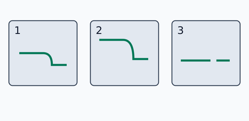
Open the full-size use-state diagram
State 1 is the parked position, 2 is the working position and 3 is unplugging. Follow the cable at each transition: a route that looks relaxed while parked may tighten as the laptop moves. Check whether the connector can be gripped without dragging the dock and whether the cable or housing is forced against an edge. The shapes indicate actions, not approved bend radii.
- With devices safely disconnected, measure the actual cable from the manufacturer's relevant connector references and trace a flexible string along the proposed path. Include changes in height and the path around obstacles; mark unknown dimensions rather than guessing.
- Place the laptop at its normal working and parked positions. Without forcing a connector, check that the unplugged cable can follow each path. Record the longest observed route and what moves.
- Compare a closer dock location with the original. Check reachable ports, support, ventilation and the manufacturer's instructions; do not cover vents or route cables where a chair wheel can crush them.
- Use the route allocation to change cable length, two measured route segments and a chosen allowance. A negative remainder reveals a mismatch between those inputs; a positive remainder does not verify bending, strain relief, electrical compatibility or performance.
- If considering a replacement or extension, check the actual devices' and cable manufacturer's specifications for the required connection and power. Test the chosen setup in the real working positions without forcing plugs; seek a compatible alternative when requirements are unknown.
Observe parked, working and unplugging as distinct states
Parked. Put the laptop in the place it occupies when the desk has been cleared for another task. If it sits closed below a monitor stand, identify where the port housing would go and where loose cable can rest. A short connection may appear to fit when the machine is parked because the cable bends in the open space that the computer will later occupy. Sketch which portion of the desk has to remain usable for writing or setting down an object. In a shared work area, note whether another user moves the cable aside, and how they leave it for the next user.
Working. Place the disconnected laptop and any usual stand as they are used. Include the maximum ordinary positions within the intended routine, whether that means sliding toward the keyboard, lifting onto a stand or turning a little toward the user to reach a side port. Check the first section each time. Look under the stand for feet that change what can pass over the desk. A physical contact near the plug can occur even when there is extra route length. Check the plug's outline at the port reference as well as the direction of its departure from the desk.
Unplugging. The user's hand needs space on the correct side of the housing. Follow the manufacturer's directions and use a disconnected cable near the port if you are rehearsing the motion; don't tug on a connected unit to see how far it can go. Determine whether the dock has a suitable support and whether it shifts under the movement you expect. The plug needs a clear line out of the connector, plus room for the hand that holds it. A dock underneath a narrow shelf can fit in its resting rectangle and conceal the very ports that need routine access.
Write down what occupies the same position across these states and what changes. If the route physically belongs to a fixed desktop and the laptop is the only moving object, focus on the segment between the host and the first resting point. If the dock is moved to reach a particular port, the second segment and other dock leads acquire motion too. For each candidate placement, choose the most demanding ordinary state and note why it was chosen. A parked cable can remain your visual reference, while a work or unplug position supplies the measurement the layout must accommodate.
Check the states between the states
One useful test is to watch a midpoint. A laptop raised to a stand and set down at the endpoints has a third position as it passes around the foot or over the edge of that stand. The middle movement can be the first place where the cable crosses another object. Likewise, a drawer that opens below a fixed desk may clip a wire during travel even though the wire appears clear at both the open and closed endpoints. With the real cable disconnected and the furniture moved slowly by its intended controls, see whether the proposed line passes through those intermediate spaces.
For a sit-stand desk, identify what rises together. A dock on the desktop and a laptop positioned on the desktop typically share its height changes. Their relative route still depends on objects that move along the top, but a separate power or display lead to wall equipment can change length dramatically. A fixed dock on a neighboring shelf belongs to a different side of the moving boundary. Draw both groups and cross the boundary only at an intended route, following the desk and equipment instructions. Compare the route at representative points you actually use and at the permitted limits needed for the intended setup.
Add a second operating state if the office must switch between private and video-call positions. A web camera cable or external screen lead can run into the same opening even when the host lead has enough allowance. Lay the path out with the actual devices safely disconnected and identify which of the other leads would restrict movement if the dock were moved. The goal is to make the state that changes explicit, not evaluate a full set of arbitrary desk poses. A route needs to accommodate normal movement that was known when it was planned.
Diagnose the contact before choosing a repair
Compare a grommet with the run around the desk edge
Draw a side view through the proposed departure from the desktop. In an edge route, mark the lip, thickness of the top or rear apron, and any clearance to the wall. In a pass-through route, mark where the opening begins and ends through the top. The hole has to accommodate the connector envelope during installation or removal, which can be larger than the cable diameter in use. Count the segment to the opening, the change of level and the segment to the dock. Follow the equipment and desk directions for the intended cable support, and check that the selected entry does not interfere with other objects using the same opening.
A hypothetical desk offers one available opening on the left and a clear back edge on the right. The laptop has to sit with its host port toward the right to keep the user's preferred working position. The left opening might appear closer to the dock in a photograph but send the flexible lead around the back of a monitor riser twice, once around its leg and again below the desk to the dock. Trace each complete route. If the edge route follows an area reached by a drawer, include that constraint as well. Writing down the routes prevents the option with the shortest isolated segment from being mistaken for the shortest usable overall route.
If you are specifying rather than using existing furniture, ask for the clear aperture, the position of any internal mounting bar and how the cover will close around the selected cable. Record what has to go through first if the housing cannot pass once other leads are installed. A pass-through that accepts all the plugs individually can still be hard to service if the first cable can only be removed after several others. Compare an open-sided route as a provisional mock-up without cutting the worktop, then decide with the furniture supplier how the permanent opening should be supported.
If the cable cannot reach the working position
Start from the last useful reference point that still has freedom. Check whether the route can move around the obstruction in a shorter direction while maintaining the equipment's requirements. A different path through an open slot may reduce a detour and still keep the cable out of a drawer. Moving the first guide might also give the laptop more usable movement without changing how the longer segment is kept clear. Test both before choosing where to install a permanent guide. Plan the line so that an occupant does not lean against it when writing or draw it across a seldom-used corner of the keyboard.
Moving the dock closer is often easier to compare than changing all the cables. Try the same port and routing direction in its new position, then retest the dock's other connections. The shorter host route might push the dock's power connection toward an edge or bring ventilation openings close to other objects. If the dock has to leave the desk in the new arrangement, include the change of height and the space for reaching any port used regularly. Keep the previous measurements. That gives you a baseline if the move solves the original symptom and creates a less accessible connection.
The laptop itself can sometimes move instead. A different angle may align the physical port with the existing path, though it can change screen position or the space needed for a writing surface. A port on another side may have different functions even when its connector looks similar. Confirm in the laptop's documentation whether the proposed connection supports the required equipment and only then compare its route. If the laptop has fixed daily positions for a reason, think of those positions as boundary conditions rather than resolving a cable problem by narrowing what the user can do at the desk.
If the plug can reach but is pressed against something
Trace the housing and the first part of the flexible cable. An edge can prevent a housing from lining up with the port before any cable length is used. A grommet placed too near the connector may demand an immediate turn where the product requires room. Draw a second view at the same height as the port so that you can compare what a top view hides. If moving the dock leaves the same plug pressed against a lip on the laptop stand, changing the host side guide or the local position of the stand is a more targeted trial.
Spare length sometimes exaggerates contact because a large loop is pushed into an area occupied by a cupboard door or desk support. The outline you want to observe is the fully relaxed path under expected movement, including where the excess can rest. Test it with a loose line first, without taping into a tight bend. Any proposed adapter that changes the angle of a port is a separate hardware decision. Consult compatibility and physical support information for that specific device and component rather than assuming the shape alone will fix the issue.
If the dock moves when a cable is removed
Note which plug the user tries to remove and in which direction the movement occurs. A dock sitting on a narrow shelf might be pulled outward because a hand cannot reach around the back to work with the connector. A docking station at the edge of a crowded table might shift because the route conditions push against it whenever the laptop is moved. These actions leave different evidence. Compare a dry demonstration with the device stable on its intended surface and no cable under tension. A successful alternative should leave practical access for the actual connect and disconnect actions, not just place the dock beyond sight.
After an adjustment, look at every lead still attached to the dock in the intended setup. It is often the collection of display, power and peripheral leads that prevents the short host path from moving. Note which leads have a nearby fixed point and which respond to a dock shift or height change. Mark which ones are usually left connected and which are removed during travel. A cable bundle can be helpful at a fixed part of the desk while the moving device needs a separate branch with a clear route to its port. Keep the branch point visible during the rehearsal.
If adding or replacing a cable is the remaining option
List the exact laptop and dock, the connection identified by both manuals, and the functions the desk must support. These might include one or more displays, peripherals or charging, depending on the actual hardware. Look for the cable requirements expressed by the manufacturer. A connector shape can be shared by cables and ports with different capabilities. A length that works physically cannot show that a given cable or an extension will carry the needed functions. If one side has a permanently attached cable, the suitable alternative may involve the supported placement of that dock or a different compatible dock, rather than placing an unverified extension at the end of its fixed lead.
Identify whichever part of the route is longer than currently possible. A cable length comparison is easiest when the path, placement and intermediate guide remain fixed. Check the reference end of the replacement using the same standard used for the original route. If the plug is bulkier or nearby objects have been moved, check that the connection still lines up and can be removed as intended. After reinstalling according to the equipment directions, follow its verification procedure for relevant functions. Keep the observation about physical reach separate from the outcome of the device checks so the next person can reproduce or diagnose one without confusing it with the other.
Put the diagnoses back into the sketch
Give each observed case a short ID of your own and a clear statement, such as “working with the laptop on the riser” or “disconnect at the near-side port.” Under it, write the usable length, position of the guide and both route segments. If a nearby object moves, record what moves and where it is recorded in the model. A photo of an open drawer or the underside of a raised desk can explain an input that looks surprising on a plan. Label the perspective from which the photo was taken, and avoid including information from screens, cables with identifying labels or other personal details if the photograph is to be shared.
Use the route allocation to walk through one change at a time. Where the model shows a 100 mm balance, you can explore shrinking it by lengthening only the first measured segment. A resulting deficit is a prompt to change a real position or reserve allocation, not to discard the reserve simply to get a favorable result. Where the route has a bend or a branch point not represented by the diagram, leave a note next to your own dimensions to show how that was handled. Reset to the teaching values before trying a different cable or comparing a second workstation.
At this stage, you can write a useful conditional report to the person choosing equipment or furniture. “On the proposed layout, the first path is 500 mm and the second is 300 mm. The 900 mm lead has 100 mm before the movement allowance and is 50 mm short of the 150 mm target. The rear guide fixes the first path, and the dock can be moved only if its other connections still work.” That report separates three lines of work: moving a location, checking vendor requirements and deciding how much movement the furniture must provide. A generic request for “a longer dock cable” would leave all three open.
Plan a handover for a desk shared over time
For a temporary home office, the normal place for the laptop may change when the table returns to another use. Agree where the loose end goes when the laptop is away, with the actual equipment and cable care requirements in mind. A reachable position near a desk opening may be easy to connect next time yet easy to trap under a laptop stand if the way to park it is ambiguous. In a desk with more than one user, let each user show their ordinary working and parked positions. A single measured “desk setup” can hide two distinct uses that overlap at only one point.
If a cable tray is being built around the current layout, leave enough access to reach the guides and identify what each cable serves. Mark a practical point from which the host lead can be inspected or changed without dismantling unrelated wiring. A narrow raceway can be right for a run that does not move, while frequently removed leads require a different type of access. Use the furniture and hardware instructions to decide which arrangements are permitted. The project record should identify any route that depends on an unverified product before the tray is fixed to the desk.
Note which later changes will invalidate the measurements
The person receiving the drawing should know where to begin if the desk changes. Apply notes to objects and events. A new laptop stand changes the port height and may shift the laptop forward; reconsider the route up to the guide, and also check the direction of release. Moving the dock to the other side changes the host route from the guide onward and may change the feed to other equipment. Changing the monitor arm adds another moving envelope near the rear opening. Taking a cable out of a bundle can change which adjacent leads support or obstruct it. Record how to inspect the accessible segment so the new setup can be checked while it is still reversible.
If a desk alternates between a full workstation and a cleared table, compare the handover position at the same time as the working position. Set down the disconnected lead in its proposed resting location, put the laptop aside and rehearse the other table use. Then set up the workstation again and see whether the lead is available without fitting a hand behind a drawer or reaching under the desk at an awkward angle. For this setup, there are now two workspaces sharing the same supports. Routing all the excess directly onto the tabletop might aid temporary access but leave no useful place for the lead when the surface is cleared.
A contractor or furniture maker may want a single dimension. Give a number only when its endpoints and state are settled. For example, state the coordinates of the guide relative to the rear edge and the underside of the desk, then specify which drawing depicts the laptop at its highest or farthest normal position. If the housing dimensions are unavailable, put the opening and cover choice on hold rather than treating the wire diameter as a complete detail. Keep the result of the layout rehearsal with the ordering information so a substituted accessory can be evaluated before it is fixed at the measured point.
Mark the width of the route if the drawing crosses a place reserved for papers, controls or a second laptop. A single centerline can hide how much the lead will move to either side between the guide and the user's device. That small extra note is useful when adding a narrow desk shelf: the shelf may keep the same centerline distance yet remove the area where the loop normally rests during a disconnect. Leave the person's ordinary working resources in place while checking the revised position.
Before calling the route finished, ask the user to reproduce the ordinary sequence with the verified assembled equipment in its intended state and according to the manuals. The useful observation is whether the originally reported pull, contact or dock shift was resolved by the intended change. If it persists, stop at the first changed position, have the equipment disconnected according to instructions and revisit only the point that moved. You now know whose movement caused the symptom, where flexible length is actually available and what evidence a replacement must address.
See the home office layout guide for chair, desk and storage activity zones. Values entered in the comparison remain only on this page. Keep a record outside the page if the setup needs to be checked again after a change in the desk or equipment.
TRY THE EXAMPLE
Compare dock cable route allocations
Enter cable length between the chosen connector references, two measured route segments and a separately chosen movement allowance, all in millimetres.
Allowed range: 1–5000 · Step: 1
Allowed range: 0–5000 · Step: 1
Allowed range: 0–5000 · Step: 1
Allowed range: 0–2000 · Step: 1
Positive remainder under these assumptions. Check the actual use and product requirements before choosing a layout.
- Length after both route segments
- 250 mm
- Balance after chosen allowance
- 100 mm
Reference boundary — Cable length between connector references: 900 mm
Blue dashed line: comparison boundary. Red dimension: shortage.
900 − 350 − 300 − 150 = 100 mm
Trace the real curved route and connector references with equipment disconnected. A positive balance is not a bend-radius, strain, electrical compatibility or performance approval.
Teaching assumptions, not a surveyed home or a construction check. Results describe this simplified geometry or budget only. Changes stay on this page and reset on reload.