Retractable Projector Screen: Living Room Obstacles
Compare a retractable screen with a living room cabinet, door and window before mounting. Work through a dimensioned example, then map the full drop path.
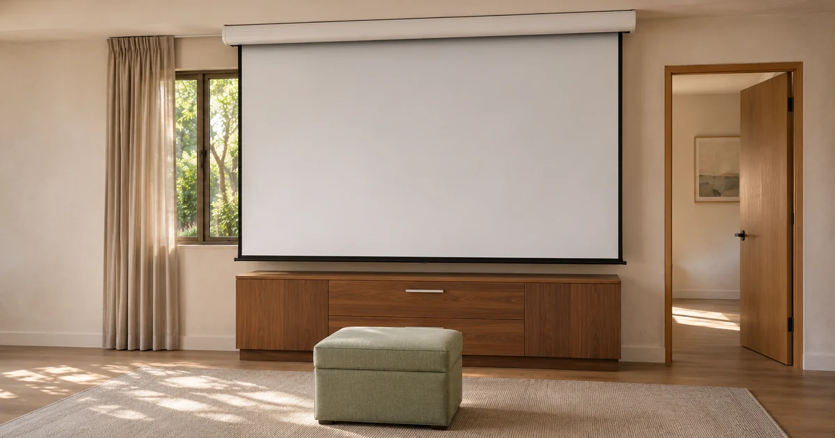
Lowered screen and cabinet projection
The cabinet projects 320 mm. The screen's 20 mm depth puts its near face 430 mm from the wall in A and 310 mm in B. The plan gap changes from 110 to −10 mm. The 800 mm bottom-bar elevation is a separate check. The cutaway also shows a window handle, the door sweep and a viewing position as separate checks.
A retractable screen can preserve a living room wall between films, but its lowered position may cross a cabinet, window handle or door. Start with the position of the screen surface and bottom bar, not the front of the ceiling case. Compare the room with the screen fully up and fully down before selecting the mounting position. If the housing-to-surface offset is unknown, keep the position undecided until the manufacturer's installation drawing is available.
Picture the moment halfway through a film when someone comes in from the hall. The cloth may already be still, but the door is about to move into the room and the person walking through will follow it. Now picture the opposite moment, when the screen is parked and somebody wants to open the window fully. A useful position has to work in both scenes. Start the sketch with the actions that must remain possible, and put the desired image on that drawing after you have identified where those actions happen.
The following teaching model uses millimetres and hypothetical dimensions. The screen and projector manuals, the room survey, and any applicable structural, electrical and exit requirements supply different evidence for the real installation.
Give each side of the room a job
Start with an annotated room sketch. Draw the television or cabinet wall, the route from the hall, the window and curtain, and the seats that people actually use. Write what normally happens on each side. A window next to the sofa might be opened every evening. The door farther from the cabinet might be the only route out. A low cabinet could contain a drawer that someone needs even during viewing. Contrast those habits with a decorative shelf that can be left alone while a film is playing. The list tells you which conflicts require a new layout and which operations can take place in a different part of the room.
Decide which items are fixed for this comparison. A built-in cabinet and an opening in a masonry wall are different constraints from a small speaker or a floor lamp that can be moved. Write down who has agreed to move each item and where it goes in normal use. An empty cabinet top in a drawing can represent a perfectly practical choice if the receiver and its cables have a permanent place elsewhere. If the receiver gets moved back after every film, the empty top is an assumption that the installation will depend upon every time someone lowers the screen.
A shared room may need three distinct operating states. In everyday use the screen is stored, window coverings work as usual, and people move through the room in normal light. During changeover the roller and bottom bar move while another person may still be standing near the wall. During viewing the screen stays down, the room may be dimmer, and seats or an ottoman may have shifted. Mark those three sketches separately. If a guest needs an explanation to find the exit while the room is dark, revise the viewing arrangement before treating the screen location as settled.
It helps to sketch a fourth state for access after installation. Someone may eventually need to inspect the case, remove a cover, reach a connection or work on the window treatment. The screen can be retracted for that job, but a beam, close-fitting recess or tall cabinet may leave too little room for the service procedure described by the product. The place needed for a technician to stand or set up their equipment also belongs on the service sketch. Standing room for the technician is a separate dimension from projected image size.
| State | Trace on the plan | Evidence to keep |
|---|---|---|
| Everyday room | Curtain travel, opening panels and normal foot traffic with the bar parked | Marked handle positions and the parked case outline |
| Changeover | Full bottom-bar sweep and any person or object in its way | Case section with the origin of the drop dimension |
| Viewing | Full fabric width, usable doors and windows, seating and optical path | Sightline from each usual seat and the relevant projector specifications |
| Service access | Access to the case, removable components and nearby fittings | The exact mounting and service drawings for the shortlisted screen |
Mark the outlines in the order you can verify them
Choose one enduring wall reference and one finished floor reference. A measuring tape stretched from a skirting board can appear to give consistent results until somebody else reads the screen drawing and starts at plaster above it. Mark the datum on the sketch and note any offset from the surface where the tape sits. If a wall panel is stepped, show the step rather than joining the two planes into one imaginary wall. A known line on the plan can be extended with a square or level so several stations along the wall can be compared from the same reference.
Take depth readings at the two screen ends and wherever a handle, window trim or cabinet change creates a maximum. For a crooked wall, mark the stations at which values were observed. An average cabinet depth could describe the floor area but miss a corner that projects farther toward the screen. If a handle has a curved face, record its outermost point and the height at which it occurs. This gives the elevation somewhere to put that measurement. Keep catalogue dimensions separate from the observed cabinet and note whether the furniture is empty, loaded or on adjustable feet.
Draw the fixed cabinet and drawers as separate objects. The everyday cabinet depth goes at the closed handle. A fully extended drawer has its own plan outline. Where the screen crosses that area, check when the drawer is used and where the user's hands will be. A cabinet door on hinges needs a moving outline near the screen end as well as an elevation. If the receiver is kept inside, find out whether its ventilation and connection access depend on leaving anything open. Those conditions affect which sketch should show the door moving.
For the screen, distinguish the case length, bracket positions, cloth width and bottom-bar length. A product called a certain size generally refers to a stated image dimension, which may leave out black borders and everything beyond them. The bar may extend past the fabric and some models have side hardware that changes the moving envelope. Record the values for the actual model and mounting method from the same revision of the drawing. Keep one column for values confirmed by a diagram and another for those you are still expecting the supplier to confirm.
A basic worksheet can record each obstacle at one station, with the height band and both the closed and open positions. For instance, a cabinet at the middle station may have one maximum when closed, while a handle on a door near the screen's right end reaches into the cloth only through part of its swing. Give them separate rows. When you move a line in the plan, revisit affected checks by station rather than changing every measurement in the room. Record which person took each new measurement if multiple people are working from the same drawing.
Read the housing section from the screen outward
Find the lowered cloth line or the manufacturer's specified reference for the moving assembly on a dimensioned side view. Locate the widest extent on the bottom bar and identify which way the fabric exits the housing under your intended mounting orientation. Then read the offsets back to mounting brackets and the case edges. The same face of the housing can be a useful installation reference, but it only predicts the cloth once you have the connecting dimension. If the sheet merely shows a case and an arrow labelled drop, ask where that arrow begins and whether it ends at the cloth or the underside of the finished bar.
If the model can be installed on a wall or a ceiling, inspect the corresponding drawing rather than rotating a sketch of one version. End caps, suspension hardware, brackets and wiring entries may change their positions. A surface that looks unobstructed at the height of the cloth may have trim or a beam immediately where the bracket needs to bear. Document your chosen mounting configuration beside the item number; a later change to a similarly named model should trigger a review of those offsets before the room marks are reused.
In a recess, mark the opening of the pocket, the inside faces, and any trim that remains when a cover is opened. Check how the manufacturer shows the case being inserted and removed. The recording dimensions here belong to access and assembly, while the downward projection used in the furniture comparison belongs to the bar. Even if the bar clears all visible trim, the service route might call for space at an end that the pocket does not have. Keep that issue with the mounting decision so a decorative finish does not conceal an unresolved fit problem.
Compare the screen plane with the cabinet
Imagine a cabinet projecting 320 mm from the wall, including its most projecting handle. In plan A the wall-to-far-face distance of a simplified 20 mm thick screen and bottom bar is 450 mm. Its near face is therefore 430 mm from the wall: the static gap to the cabinet is 450 − 20 − 320 = 110 mm. Set aside 60 mm as a chosen trial allowance, leaving 50 mm in this one direction. That reserve is an example to investigate, not a manufacturer's specification.
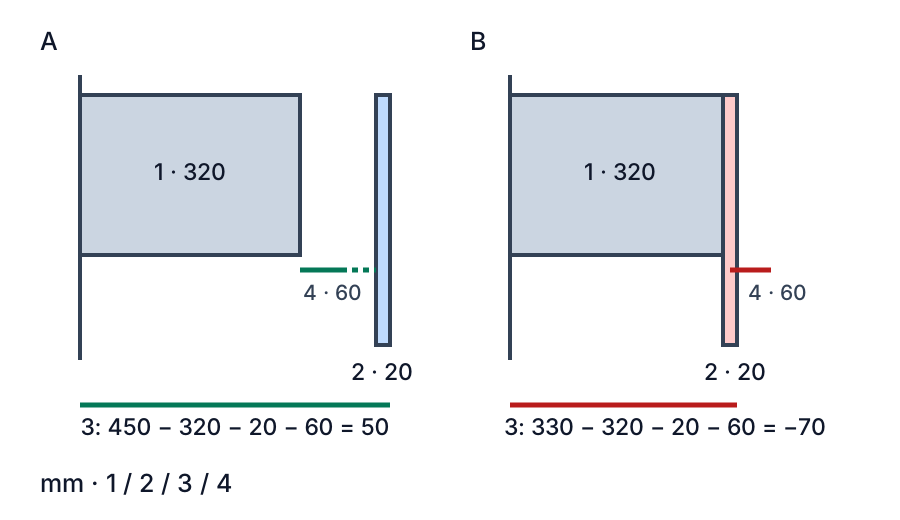
In the drawing, 1 is the cabinet projection, 2 the screen envelope, 3 the arithmetic and 4 the chosen trial allowance. Look at the line from the wall to the far face: both cases use the same datum. In plan B it is only 330 mm. The static gap is −10 mm, and after the same 60 mm allowance the balance is −70 mm. The simplified envelopes overlap; moving the screen forward may remove that overlap, but also moves the image toward the seats and changes the projector's optical distance. A different screen or cabinet position can be preferable.
Try both positions in the interactive comparison. Enter the measured wall-to-far-face distance, the cabinet's furthest projection, the screen envelope and your separate trial allowance. A positive balance describes this single section only. If a dimension is unknown, leave it blank: the result stays unknown rather than assuming zero. Check the changed position in the room and against the exact screen's installation drawing before ordering.
Check height separately from depth
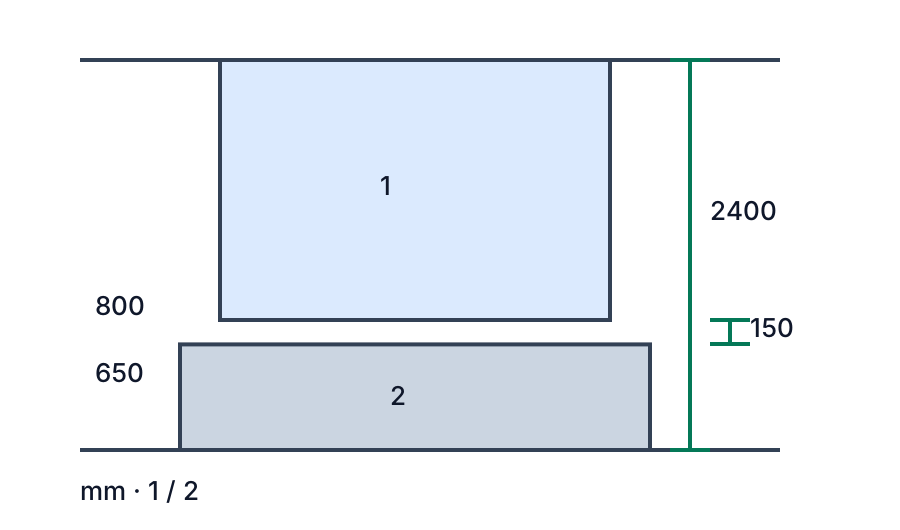
Here 1 is the lowered screen and 2 the cabinet, drawn in one elevation even though they may be at different depths. For a 2400 mm ceiling and a simplified 1600 mm drop from that ceiling reference to the bottom bar, the bottom is 800 mm above the floor. A 650 mm cabinet top is 150 mm lower. This is a vertical difference, not proof that a descending bar clears every object: the housing may sit below the ceiling, and the manufacturer may define drop from another point. Use the actual drawing and include handles, ornaments and the entire downward travel. A bar that remains above the cabinet could still obstruct an object placed on it.
The two comparisons answer different questions. The plan measures a horizontal section; the elevation compares height at an assumed reference. Do not add their positive gaps together or infer that a diagonal movement is safe. If the bottom must be raised to avoid a cabinet, a smaller image or a higher housing may affect subtitles and viewing posture. Try an outline from every regular seat, not just the centre of the sofa.
Use the two presets to find what would have to change
The moving rectangle in the plan has two faces. When the far face is the dimension you can read from the example, subtract the entire 20 mm once to place the near face. The cabinet gap is measured from the near face, so it uses that smaller wall-to-screen number. If the drawing for your screen instead locates the near face directly, record the far face by adding the thickness before using the example's form. You can calculate the direct gap between the recorded near face and the cabinet without that conversion if you are working on paper.
Reverse the subtraction to find a search boundary for this teaching section. A cabinet projection of 320 mm and a moving thickness of 20 mm require a far-face distance of 340 mm to reach zero nominal gap. Adding the chosen 60 mm to that sum gives 400 mm to reach zero after the allowance. In the lab, try 340 mm and then 400 mm with all the other inputs held still. At 340 mm the outlines meet and the allowance is completely absent. At 400 mm the outlines are apart by the chosen allowance, with no additional balance. Neither is an installation target.
The same equation can ask what furniture would satisfy a fixed screen position. At B, keep the far face at 330 mm, the thickness at 20 mm and the allowance at 60 mm. The hypothetical cabinet would have to project at most 250 mm for a nonnegative allowance balance in that section. That is a 70 mm reduction from the original envelope. Measure the actual handles and the furniture depth before deciding whether a different pull could achieve anything close to that difference. A nominally shallow replacement cabinet also needs the back space required by its installation and the connections it contains.
These one-variable comparisons show the scale of each choice. Moving the screen 70 mm forward from B changes the lens-to-image relationship and the bottom bar's location at the door. Shortening the cabinet projection by 70 mm changes storage and perhaps leaves less service space behind equipment. A combination can share the change across both items. Keep the allowance value visible while comparing alternatives so their signs have the same meaning, and then rerun a chosen combination with the actual product and room dimensions.
There are good reasons to leave the exact available gap unresolved during an early purchase search. A manufacturer might supply a cloth thickness while omitting the cross-section of the bottom bar. Two measuring passes could place a cabinet handle at different depths because the floor is uneven or the cabinet was shifted to record cable access. A narrow gap based on the most favourable numbers deserves a better section drawing. Keep the values that have a known range on the worksheet and leave a blank for any dimension for which you have no credible bound.
If you have two plausible measurements, you can compare them transparently. In the imaginary A case, suppose the measured cabinet projection is anywhere from 315 mm to 325 mm depending on the station. With the far face 450 mm and thickness 20 mm, the static difference ranges from 115 mm to 105 mm. The smaller static gap leaves 45 mm after the same 60 mm reserve. It tells you which station merits attention in that horizontal section. It says nothing about a separate lamp standing in front of the wall at a different station or a handle swinging farther during use.
Put the bottom bar and the image on their own height lines
On the elevation, give the ceiling, case, drop origin, lowest bar point and bottom of the visible image individual marks. Their order and spacing come from the screen construction. A strip of black fabric above an image can lower the image without moving the mounting hardware; the bar still needs a clear route through that lowered position. Likewise the bar can be below the picture. Estimate the sightline using the visible image marks and assess furniture clearance using the physical envelope marks, with units and reference names written beside both.
For a second hypothetical calculation, keep the earlier 2400 mm ceiling and 1600 mm drop but place its actual origin 75 mm below the ceiling in a proposed bracket setup. The assumed bar bottom would be 2400 − 75 − 1600 = 725 mm. The plain cabinet top at 650 mm would be 75 mm below it, half the difference shown in the teaching elevation. If an item on that top reaches 760 mm, it rises 35 mm above this proposed bar-bottom line. Draw the item at its real horizontal station and depth to see whether it even enters the falling bar's section.
A real floor can slope. If you measure from the floor below the centre and then take the cabinet height at one end, mark where each vertical measure began. A level line can provide a common reference across the width. A rug or adjustable foot may change where a cabinet top ends up in the final layout. Record final finishes and furniture placement on the survey sheet. When the actual product drawing is available, a few clearly located measurements are preferable to decimal precision from a nominal room height.
Take a vertical section through a window handle and one through a door handle if those parts are close to the outer ends. Put the lower edge of the parked bar and both extents of the actual case on those sections as well. A revolving window handle can have a protruding part at a different height when unlocked. A hinged or inward-opening window may bring a sash across the marked cloth plane as it opens. In a room where the window is needed during viewing, check that normal opening and closing remain possible with the screen fully down.
Map the interferences by movement, with the room still usable
The most revealing door position can be between closed and fully open. Draw its pivot at the hinge, include the thickness of the leaf and its projecting handle, and follow the portion that comes nearest the screen across the entire normal swing. For a quick test, put the proposed plane on the floor with removable tape and note where the door's leading edge and handle pass above it. Check the heights where crossing occurs. Doorway space matters to the people using it, including those carrying an object that makes the normal path wider. Preserve the available exit path without assuming an electrical screen will respond.
A sliding door can still have a handle, a latch and an access pocket that occupy space at the edge of the screen. Draw its moving length from closed to open. If it is outside the room but the person reaches around the opening, map the space needed by their hand without using the screen as a stop. A second door on the other side of the seating area may enter the projector beam while leaving the screen intact. That might briefly interrupt the image during an arrival, a different consequence from blocking the door or damaging moving hardware.
Look at curtains at several stages. A curtain can have a compact stack to one side in good light and billow into the bar path when the window is open. Its rail remains when the fabric is pushed away. Check the projecting bracket and the width of all the folds with the curtain in its intended viewing position. If using the window with the screen down is a requirement, include the typical curtain positions for that action. Keep the physical checks distinct from the light-control check, since a blackout treatment can fit mechanically but still leave an illuminated strip across the image.
At the cabinet, stand where someone typically uses a drawer or reaches an outlet. Check their arm movement around the proposed plane while an assistant keeps the area clear. Use non-load-bearing marks on the walls or floor and a sketch rather than stretching a line across the doorway. Fragile belongings and connected equipment should remain out of a mock-up. If there are children or pets in the household, trace their common routes and check what they can reach at that location. Follow the supplied screen controls and use instructions rather than building a test that depends on restraining a moving bar.
Keep a separate register for overlaps found during the changeover. Write the room state, the object, the position of the bar when the outlines intersect and what would change the outcome. An entry like “speaker right of centre, bar reaches shelf height while lowering” gives somebody enough information to repeat the check. “Screen fits wall” does not. If the speaker moves to a shelf outside the width of the moving assembly, record the new shelf location and confirm the cables and controls can stay there for both viewing and daily use.
Let the seating and projector revise the plan
When the screen moves forward, there are two different distances to record. The viewer-to-picture distance starts at the user's seat and ends at the image plane. The lens-to-screen distance starts at the projector lens reference given by the manufacturer. Moving the screen toward seats may shorten both if the lens is behind the screen on the same axis, but an off-centre or short-throw setup has its own constraints and drawing. Write the two distances in different rows and name the endpoints so a dimension taken to the cabinet face cannot silently stand in for either.
Compare the proposed image width with the manufacturer's supported throw range or placement chart for the exact projector and lens. In a simplified centred layout where the product defines throw ratio as distance divided by image width, a 2000 mm image at 2500 mm lens distance gives 1.25. Shortening that distance to 2380 mm with the same image gives 1.19. These two ratios demonstrate the effect of moving the screen by 120 mm in that assumed geometry. The manufacturer's chart determines whether the selected setup supports either, including the available adjustments and any focus or image-size limits.
Inspect the optical axis in plan and elevation. Lens offset, shift range and orientation can change where the picture lands relative to the lens mount. A cabinet setup may lift the projector over a soundbar but put the optical path through a hanging fixture; a ceiling setup can leave power and video connections difficult to reach. Check the product's diagrams for the actual model and mounting configuration. A digital adjustment that alters the projected image does not create mounting space, a shorter physical throw or a place to route cables.
Walk through the usual seats with the proposed picture rectangle marked. For a sofa corner, check whether a tall person sitting in front would obscure a lower subtitle line. For a chair farther to one side, check viewing angle and whether the cabinet edge or an open door blocks part of the picture. If the lower edge is moved to clear an object, use a new picture mark and repeat with the other seats. Different screen materials can have different viewing characteristics; the geometry check marks what can be seen from the seat and leaves image performance to the model documentation and a suitable demonstration.
A frequent trade-off is between a smaller picture at the same wall and a larger picture on another wall. In the first option, a smaller overall assembly may leave more room at the screen ends and allow the bottom bar to stop higher depending on the product. In the second, shifting to a different wall can keep a larger image while changing the viewing direction, light sources and cable lengths. Carry over the viewing habits from the first room sketch, then draw fresh door, curtain and optical checks for the second wall. The measurements from a clear first wall do not establish the conditions at a second.
Settle the candidate with a real-room handover
Give each candidate a short name and a drawing date. Record the room states it accommodates, the changes it needs and the dimensions still awaiting evidence. One useful decision record might say that A clears the static cabinet section with the chosen reserve, but still needs a checked door swing at the right end and the manufacturer's throw chart. B crosses the cabinet section with the current furniture, so it remains a candidate only if the furniture is changed or the bar travels at a different eligible height. This leaves an actionable choice without turning a single calculated number into blanket approval.
Collect the screen model code, case and bar section, exact case length, allowed fixing details, mounting surface and lens information together. Mark which sheet shows the specified wall-to-cloth offset and which drawing establishes the origin and end of the drop. Share the room sketch with the installer before any decision depending on a concealed structure or wiring route. If an appropriate fixing or power route cannot be confirmed for the exact position, treat that position as pending and compare one whose practical dependencies can be checked.
Keep an unobstructed path through the room while comparing the geometry. Verify room changes with the users who will live with them; a temporary chair rotation or a relocated remote can make sense in one household and become a nuisance in another. During a mock-up, stop at the first clear obstruction and record it instead of pushing hardware or moving a door through a sample. After a proper installation, revisit the records for the actual screen and room. Check the posted operating instructions, door and window access at both ends, the optical result, and the places where anyone must stand to use storage or access controls.
A final observation is easier to interpret when the room is back in ordinary use. Put the customary equipment back, park the curtains the way people do in the evening, and return the chairs to the places you tested. Use the usual viewing operating sequence while keeping people clear of the moving assembly. Observe whether an unexpected task appears, such as fetching a charger from a drawer near the lower bar or opening a window at the other end. Record the new task at the relevant place on the sketch. That instance gives meaning to the room-state plan when the cabinet or seating changes again.
Three plausible room changes, with different consequences
Keep the cabinet and move the screen. This is the most direct geometric response when a closed cabinet crosses the travel of the bar. Work through the mounting options that put the cloth at the new plane, checking both bracket locations and the case body. Then mark the projection lens and the door swing at the new plane. A small advance that solves a conflict at the cabinet can expose the screen corner to a door pivot farther into the room. Check the whole width before committing to the brackets, and see whether the wiring path also needs to cross a new part of the ceiling.
Keep the screen line and redesign the cabinet zone. This can preserve a known optical setup or keep a route to the window free. Name the physical source of the excess projection before replacing the cabinet. If the depth reading includes a handle, the next useful dimension is the body plus its installed position with connections and back clearance. If the body is shallow enough and its current position depends on loose leads, ask whether those leads can be routed in a manufacturer-approved way and kept accessible. For a new cabinet, check working storage, open panels and any soundbar or receiver that must stay in the installation. Use the same height stations when comparing the revised cabinet.
Move the picture to a different wall. Draw the existing seating rather than assuming the room rotates as a set. A sofa that faces one wall may block the best projector position for a perpendicular wall. A different arrangement might also move seats away from window glare or make conversation awkward between screenings. Make the new plan on a separate sheet and retain the first one for comparison. The trade-off becomes legible if each sheet has one viewing rectangle, one unobstructed walking route, one designated position for audio equipment and a callout for the mounting information that still needs to come from the actual product.
Two reasons to reopen a drawing near the end
First, a proposed furniture change can alter where people stand without changing any object dimension. A new side table may fit beside the screen and still attract people to a spot where they reach across the taut cloth to pick up a remote. Draw the standing position and the actual reach from the furnishing to that point. A different home for the remote can resolve the conflict without moving a measured plane.
Second, the selected product may differ from the shortlist illustration. Record both the model identifier and the detail number for your mounting configuration. Check that the case, bar, brackets, fabric and image dimensions all refer to that configuration. If a substituted model has a wider bar, revisit the two ends even when the nominal image width remains the same. If it puts the cloth at a different offset, repeat the cabinet and window sections and compare the lens-to-screen dimension again. This review is easier to schedule before a decorative recess is closed and before the cabinet is ordered.
Rehearse the room in both states
- On a sketch, mark the wall, the actual ceiling case, its specified surface offset and bottom bar, and the cabinet's furthest projection. Mark the proposed screen width including borders and casing; the image area alone is smaller.
- With the screen up, check the window, curtains, cabinet doors and daily walking route. The case, power lead and brackets still occupy space.
- With the screen down, mark its entire rectangle and trace the normal door and window-handle movements. A single gap at the cabinet cannot establish that the full screen width clears a door swing. Do not block an exit or rely on retracting the screen in an emergency.
- Compare alternative positions using the living room layout guide. A screen moved forward changes lens-to-screen distance; use the projector manufacturer's throw and mounting data rather than assuming a projector will still focus.
- Before fixing anything, follow the screen and projector manuals and obtain appropriate structural and electrical advice. Do not drill into unknown services or improvise a support. Recheck the actual drop and movement after professional installation.
Leave a copy of the room record where the next person making a change can find it. A useful closing entry names one selected plane, one rejected plane and the reason each received that status. Include the room states in which a conflict appears, the particular screen and projector under consideration, and the open questions that still prevent an order. If a future cabinet projects farther into the room, that record gives the next measurement a known origin and tells you which section to recalculate.
TRY THE EXAMPLE
Compare the cabinet and screen section
Measure from the same wall to the screen's far face. Enter the cabinet's greatest projection, screen envelope and a separately chosen trial allowance in millimetres. Empty measurements remain unknown.
Allowed range: 1–3000 · Step: 1
Allowed range: 0–2000 · Step: 1
Allowed range: 1–500 · Step: 1
Allowed range: 0–1000 · Step: 1
Positive remainder under these assumptions. Check the actual use and product requirements before choosing a layout.
- Static gap between cabinet and screen
- 110 mm
- Balance after chosen allowance
- 50 mm
450 − 320 − 20 − 60 = 50 mm
Measure the selected case's offset and full bottom-bar envelope, then test doors, the complete drop path, viewing position and structural and electrical requirements separately. This one-dimensional teaching section cannot approve an installation.
Teaching assumptions, not a surveyed home or a construction check. Results describe this simplified geometry or budget only. Changes stay on this page and reset on reload.