Fold-Down Wall Desk Clearance: Check the Hinge Sweep
Check a wall desk from vertical storage to horizontal use. Calculate its hinge sweep, spot a false fit at 60 degrees, and record the evidence before drilling.
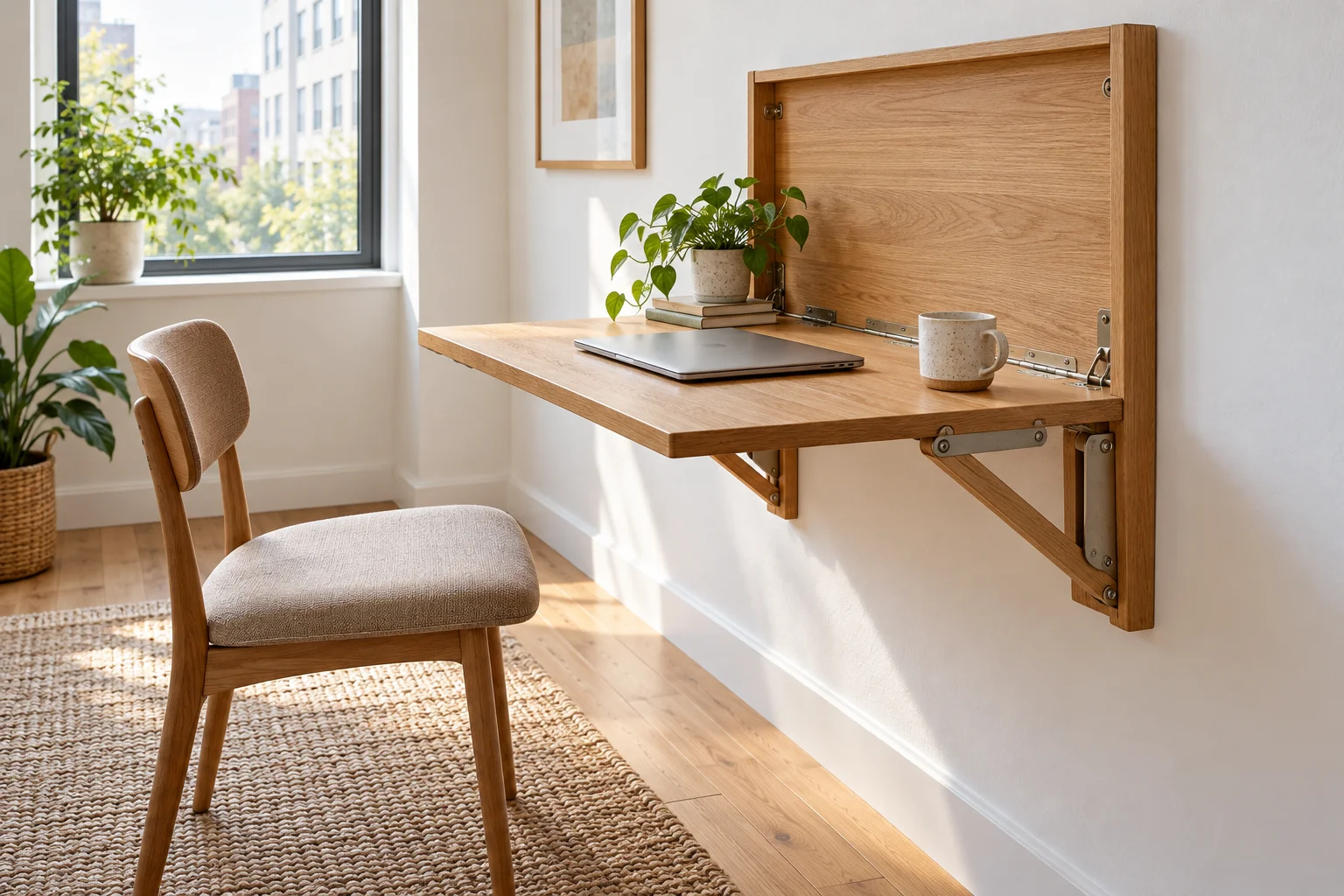
A wall desk can look practical in a photo with its panel partly lowered yet hit a cabinet before it reaches its working position. This guide follows a panel that stores upright, hinges at the lower edge and folds down to horizontal. It does not cover a top that hangs below its hinge when stored, a pivoting shelf or a multi-link mechanism. Match the mechanism before borrowing the calculation.
The worked example is an original hypothetical section, not a surveyed room, a tested product or an installation approval. Millimetres describe lengths and degrees describe rotation. The immediate decision is whether the opposing furniture must move before the candidate desk is worth taking to an installer.
Draw a side section through the hinge
Measure from the vertical plane containing the hinge axis to an opposing reference plane. Then measure any cabinet or other obstruction projecting from that reference toward the desk. You need both measurements along the same horizontal direction, at the relevant heights. If you instead measure directly to the cabinet front, its projection is already removed; set extra occupation to zero rather than deducting the cabinet twice.
Our section has a hinge-to-reference distance of 680 mm, a cabinet projecting 100 mm into it, and a panel 600 mm long from the hinge axis to its far edge. The zero-degree position points upward; 90 degrees is horizontal. The diagram is a vertical section, even though its simple line resembles a door in plan.
Why a partial opening gives a misleading answer
For a zero-thickness panel, horizontal projection is panel length × sin(angle from upright). At 60 degrees, 600 × sin(60°) = 519.6152 mm. The remaining space is 680 − 100 − 519.6152 = 60.3848 mm. Rounding for a room sketch gives about 520 mm projection and 60 mm remaining.
At 90 degrees, the projection is 600 mm and the remainder is 680 − 100 − 600 = −20 mm. The panel therefore fails this simplified horizontal comparison when fully lowered, despite the positive intermediate result. On this particular 0–90-degree movement, projection increases toward the horizontal endpoint. This does not establish clearance above, below or beside the panel, nor account for thickness and hardware.
| Panel position | Horizontal projection | Remainder against cabinet |
|---|---|---|
| Upright, 0° | 0 mm | 580 mm |
| Partly open, 60° | 519.6152 mm | 60.3848 mm |
| Horizontal, 90° | 600 mm | −20 mm |
Do not solve the problem by using the panel at 60 degrees unless the exact product explicitly permits that use. A smaller opening angle is a state to inspect, not a new load-bearing configuration you can invent.
Compare two physical changes
Moving the opposite cabinet 40 mm away reduces its intrusion from 100 to 60 mm, making the horizontal result 680 − 60 − 600 = 20 mm. It retains the desk depth but consumes space behind the cabinet, and the small arithmetic remainder still excludes board thickness, handles, supports and measurement error. Confirm that the cabinet can actually move and remain correctly secured.
A hypothetical 550 mm panel keeps the cabinet where it is and leaves 680 − 100 − 550 = 30 mm. It gives up 50 mm of work depth. That may affect a laptop, external keyboard or paper layout; use the intended equipment to evaluate it. These are different candidate products or approved layouts, not instructions to cut a panel or alter its brackets.
The hinge is only one moving part
Obtain the product side drawing, fixing requirements and opening instructions. A folding support arm can occupy a different volume from the board. A latch can require a hand beside the edge; a cable may pass through the same area as a moving bracket. Identify where the chair and the operator go while lowering the desk. The clear panel sweep cannot also be silently counted as an occupied standing zone.
Keep the desk unloaded during an approved opening demonstration. Observe the full sequence with supports engaging as specified. Do not stand below an unsupported panel or improvise hardware to test the layout. Wall construction, fixings, hidden services and rated loads require their own confirmation before drilling; a positive subtraction says nothing about anchorage.
Record evidence before making the installation decision
Download the opening-path worksheet (CSV). The sheet separates axis reference, panel length, obstruction projection, angle and unresolved hardware. Record the product revision and a drawing or photo reference. Mark missing readings unknown, not zero.
The interactive side-section exercise starts at 680, 600, 60° and 100. Switch to B to change only the angle to 90°. Then try a 60 mm cabinet intrusion or a 550 mm panel separately; do not change both if you want to identify which change removes the shortage. Angles accept 0–90° in 1° steps, and lengths use the displayed millimetre ranges in 1 mm steps. A blank value suppresses the calculation. Reset returns to A, and reloading discards your edits.
The first diagram shows the partial opening and the dashed horizontal endpoint; the second makes the change from positive to negative remainder visible. Neither is a complete moving-solid simulation. Before choosing a desk, check the actual support envelope and an occupied working arrangement. The home office guide covers the seated workspace; the folding dining table guide addresses chair and circulation bands for meals rather than this hinge calculation.
Geometry and assumptions
This fictional vertical side section treats a 600 mm desk panel as a zero-thickness line hinged at its lower edge. It starts upright against the wall and folds down through 0–90 degrees. The opposing reference plane is 680 mm from the hinge plane; a cabinet projects 100 mm back into that strip. This is not a plan-view door diagram.
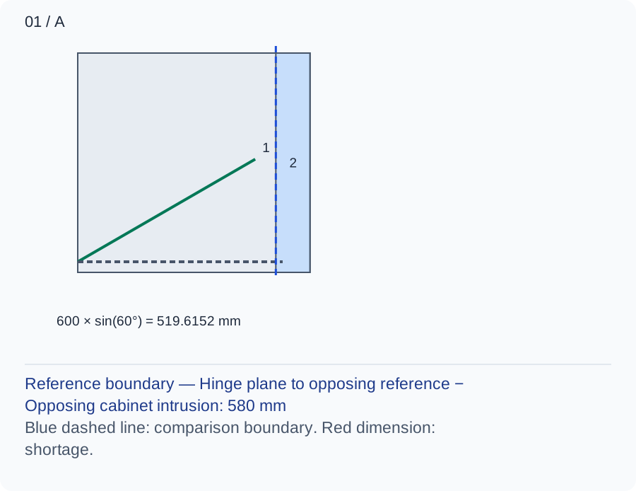
The sloping line in diagram A is the desk at 60 degrees from upright. Its horizontal projection is 600 × sin(60°) = 519.6152 mm, leaving 680 − 100 − 519.6152 = 60.3848 mm. Read the dashed horizontal line as the 90-degree endpoint, not as a safe working position already checked.
Numbers and marks identify the items described here; use the stated dimensions rather than measuring the screen.
Vertical section: 1 is the desktop rotating from upright; 2 is the opposite obstruction. Dashed line is horizontal at 90°. The line omits board thickness and brackets.
| Input | A | B |
|---|---|---|
| Hinge plane to opposing reference (mm) | 680 | 680 |
| Panel length from hinge axis (mm) | 600 | 600 |
| Angle from upright storage (°) | 60 | 90 |
| Opposing cabinet intrusion (mm) | 100 | 100 |
Changed conditions and evidence
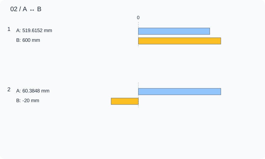
Diagram B changes only the angle to 90 degrees: projection 600 mm and remainder −20 mm. Stopping at 60 degrees hides the failure; it does not create an approved desk position. A 40 mm relocation of the opposing cabinet would make its intrusion 60 mm and the remainder 20 mm, still excluding thickness, supports and the person.
| Calculated relationship | A | B |
|---|---|---|
| 1. Rotating panel projection | 519.6152 mm | 600 mm |
| 2. Remainder after the stated allowance | 60.3848 mm | -20 mm |
Obtain the installation side drawing and permitted opening sequence. Check the full panel, supports, latch, hand position and cable loop through the entire movement. Confirm fixings and wall suitability separately; do not drill or use a partly open panel based on this line model.
TRY THE EXAMPLE
Follow the wall desk from vertical to horizontal
This fictional vertical side section treats a 600 mm desk panel as a zero-thickness line hinged at its lower edge. It starts upright against the wall and folds down through 0–90 degrees. The opposing reference plane is 680 mm from the hinge plane; a cabinet projects 100 mm back into that strip. This is not a plan-view door diagram.
Allowed range: 1–3000 · Step: 1
Allowed range: 1–3000 · Step: 1
Allowed range: 0–90 · Step: 1
Allowed range: 0–3000 · Step: 1
Positive remainder under these assumptions. Check the actual use and product requirements before choosing a layout.
- Rotating panel projection
- 519.6152 mm
- Remainder after the stated allowance
- 60.3848 mm
600 × sin(60°) = 519.6152 mm
Obtain the installation side drawing and permitted opening sequence. Check the full panel, supports, latch, hand position and cable loop through the entire movement. Confirm fixings and wall suitability separately; do not drill or use a partly open panel based on this line model.
Teaching assumptions, not a surveyed home or a construction check. Results describe this simplified geometry or budget only. Changes stay on this page and reset on reload.